Product Page

Arduino 4 Channel Relay Module Board

0

Need some help?

Contact Us

Product Ships in

2-3-business Days

Payment Methods:

Arduino 4 Channel Relay Module Board in Lahore Pakistan

Here’s a detailed product description and usage guide for an Arduino 4 Channel Relay Module that you can use on your website. It includes key features, specifications, application areas, and a simple guide on how to use it.


🔌 Arduino 4 Channel Relay Module Board – Product Details

Product Description

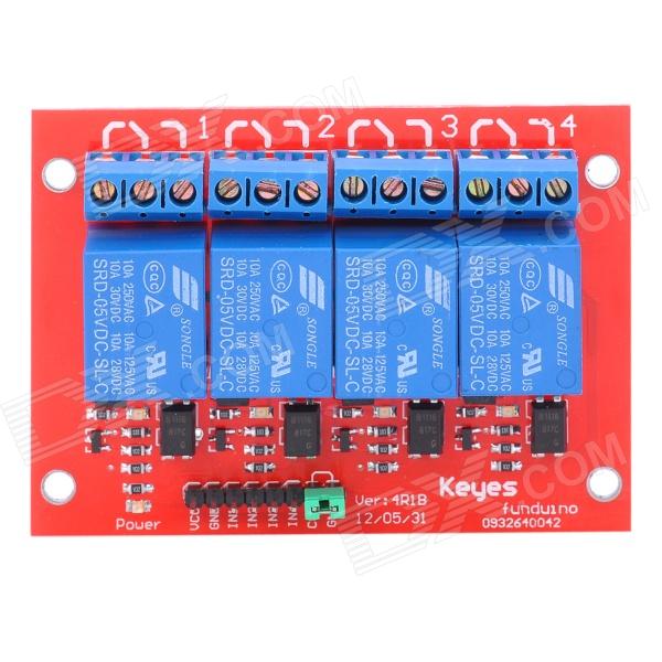
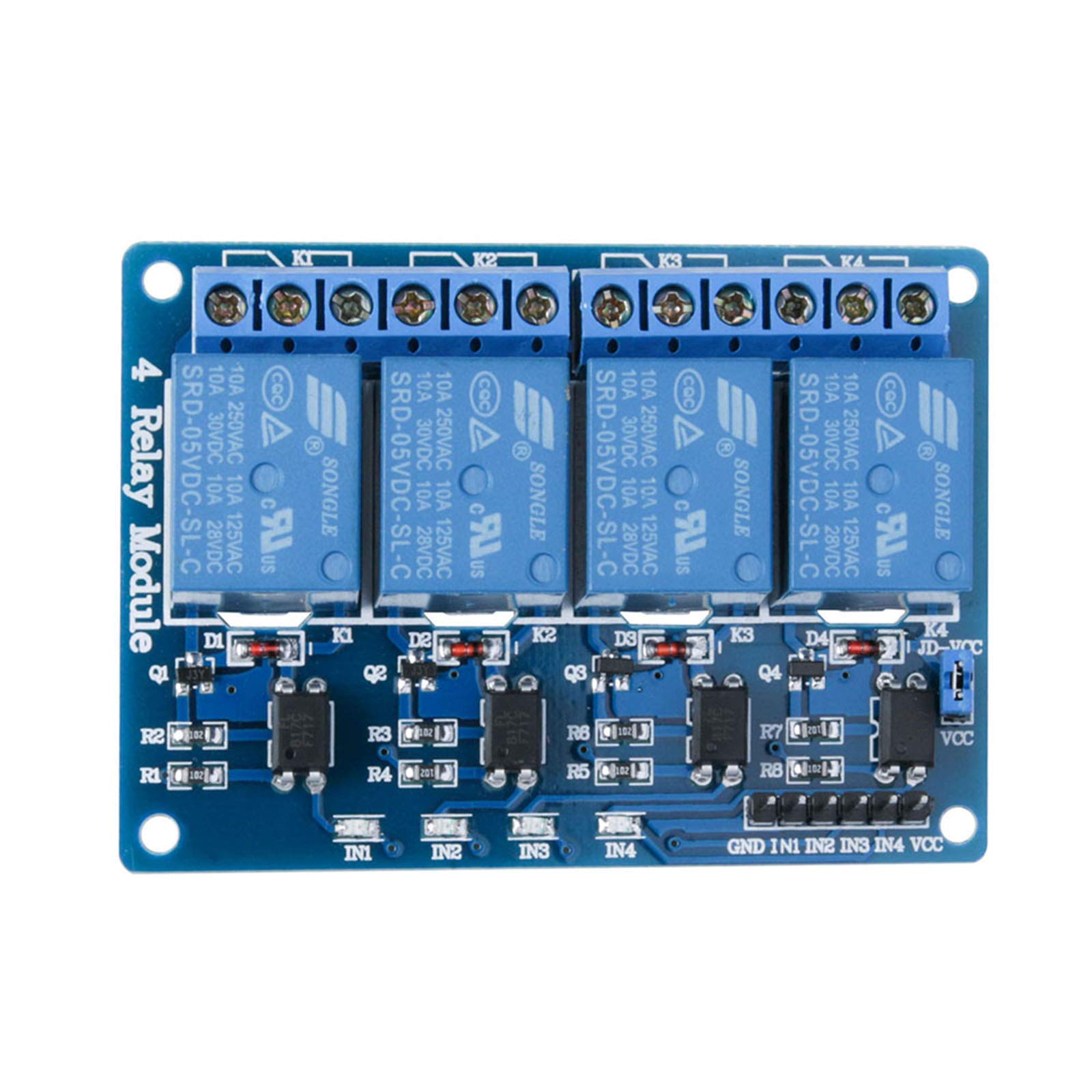
The 4 Channel Relay Module is a convenient and reliable way to control high-voltage appliances or devices using your Arduino, ESP32, Raspberry Pi, or any other microcontroller. This relay module can be used to control AC (up to 250V) or DC (up to 30V) devices like lights, fans, motors, and more.

Each relay can be triggered independently through digital output pins and provides both normally open (NO) and normally closed (NC) connections.


🔍 Key Features

  • 4 Independent Relays: Control four separate devices from one module.

  • 🔧 Opto-Isolated Inputs: Provides protection to your microcontroller from voltage spikes.

  • 💡 Status LEDs: Each channel includes an LED to indicate when the relay is activated.

  • 🔌 High Voltage Support: Can switch AC voltages up to 250V @ 10A.

  • 🔋 Low Trigger Input: Compatible with 3.3V and 5V microcontrollers (Arduino, ESP32, etc.)

  • 🔒 Screw Terminals: Easy connection to high-voltage devices without soldering.

  • 🧯 Safety Features: Optocoupler isolation protects against electrical interference.


📦 Specifications

Parameter Details
Relay Channels 4
Operating Voltage 5V DC
Trigger Voltage 3.3V or 5V (Low-level trigger)
Relay Type SPDT (Single Pole Double Throw)
Max AC Load 250V @ 10A
Max DC Load 30V @ 10A
Dimensions Approx. 75mm x 55mm x 18mm

⚙️ How to Use the 4 Channel Relay Module

🔗 Connections

Relay Module Pin Connect To
VCC 5V of Arduino or MCU
GND GND of Arduino or MCU
IN1, IN2, IN3, IN4 Digital Pins (D2 to D5, for example)

🖥️ Sample Arduino Code

int relay1 = 2;
int relay2 = 3;
int relay3 = 4;
int relay4 = 5;

void setup() {
pinMode(relay1, OUTPUT);
pinMode(relay2, OUTPUT);
pinMode(relay3, OUTPUT);
pinMode(relay4, OUTPUT);
}

void loop() {
digitalWrite(relay1, LOW); // Relay ON
delay(1000);
digitalWrite(relay1, HIGH); // Relay OFF
delay(1000);
}

Note: Most modules use a LOW-level trigger, which means sending LOW to the input pin turns the relay ON.


🛠️ Applications

  • Home automation systems

  • Industrial equipment control

  • Remote-controlled appliances

  • Smart lighting control

  • Security systems

  • DIY electronics and IoT projects


📦 What's in the Box?

  • 1 x 4 Channel 5V Relay Module Board


🔒 Safety Note

Always be cautious when working with high-voltage AC. Ensure all wiring is done with the power off, and consider using protective casings.


Would you like a product image, wiring diagram, or PDF datasheet to add to your website as well?

You said:
Arduino 4 Channel Relay Module Board pictures
ChatGPT said:
https://m.media-amazon.com/images/I/71-LmPoCd9L.jpg
https://store-usa.arduino.cc/cdn/shop/files/A000110_02.front_1200x600_crop_center.jpg?v=1727104149
https://hobbycomponents.com/183-large_default/4-channel-5v-relay-module.jpg
https://www.sector67.org/blog/wp-content/uploads/2014/11/sku_144762_1.jpg

Here are several high-quality images of the Arduino 4‑Channel Relay Module Board (also sometimes referred to as a relay shield):

  1. A standard 4‑channel relay board featuring four blue relay units and associated circuitry.

  2. The Arduino-branded 4‑Relays Shield, designed to snugly mount on Arduino boards, complete with status LEDs and screw terminals.

  3. An alternative generic blue PCB version with explicit relay components and wiring layout.

  4. A red PCB version illustrating screw terminals and clear component arrangement.


Quick Explanation of the Interface and Features

These images typically showcase the module's layout, including:

  • Four relay components (usually blue rectangular blocks).

  • LED indicators for each channel to show relay activation.

  • Screw terminals labeled COM (common), NC (normally closed), and NO (normally open) for connecting external loads.

  • Control pins (IN1–IN4), plus VCC and GND for power and control signals.


Technical Specifications (Based on Local Listings)

From Pakistani retailers:


Pinout & Usage Overview

Based on tutorial references:

  • Power:

    • VCC (DC+) — Connect to 5 V supply.

    • GND (DC–) — Ground, must be common with your microcontroller.
      Arduino Getting Started

  • Control Inputs: IN1 through IN4 correspond to each relay. Modules often use low-level trigger, meaning:

  • Relay Output Terminals:

    • Each relay provides COM, NC, and NO terminals.

    • Use NO when you want the circuit completed when relay is activated; use NC when circuit should break upon activation.
      microsolution.com.pkDigilogElectronics

Some modules offer jumpers to switch between active low and active high triggering as needed.
Arduino Getting Started


How to Wire & Use (Arduino Example)

Wiring Setup

  • Power: Feed a stable 5 V (not directly from Arduino if driving multiple relays; consider an external regulated supply) to VCC and connect GND to the Arduino’s ground.
    Arduino Getting Started

  • Control Lines: Connect IN1–IN4 to digital output pins on the Arduino.

  • Load Connections:

    1. Connect one end of your appliance to the COM terminal.

    2. The other wires go either to NO or NC, depending on whether you want the device off by default or on.

Example Arduino Code (Simplified)

const int relayPins[] = {2, 3, 4, 5}; // Connect to IN1–IN4

void setup() {
for (int i = 0; i < 4; i++) {
pinMode(relayPins[i], OUTPUT);
digitalWrite(relayPins[i], HIGH); // Keep all relays off at start
}
}

void loop() {
for (int i = 0; i < 4; i++) {
digitalWrite(relayPins[i], LOW); // Turn on relay
delay(500);
digitalWrite(relayPins[i], HIGH); // Turn off relay
delay(500);
}
}

If the module uses low-level triggering (most do), setting the pin LOW activates the relay.
DigilogElectronicsHallroadlahore.pkArduino Getting Started

Power Consideration

If all four relays draw about 15–20 mA each, that's 60–80 mA just for the coil, plus any loads. While some modules may tolerate Arduino’s onboard 5 V, using an external regulator can avoid power issues.
Arduino Getting Started


Summary Table

Feature Details
Channels 4 switched relays
Trigger Type Usually active LOW (selectable)
Input Control Voltage 5 V TTL (15–20 mA per channel)
Output Capability 10 A @ 250 VAC or 30 VDC (NO contacts)
Connections COM, NC, NO with screw terminals
Indicators LED for each channel
Size ≈ 75–76 × 55–56 × 17–18 mm